- 您现在的位置:买卖IC网 > Sheet目录475 > MC33591MOD315EV (Freescale Semiconductor)BOARD EVAL MC33493 TANGO3 RF
Freescale Semiconductor, Inc.
STATE MACHINES
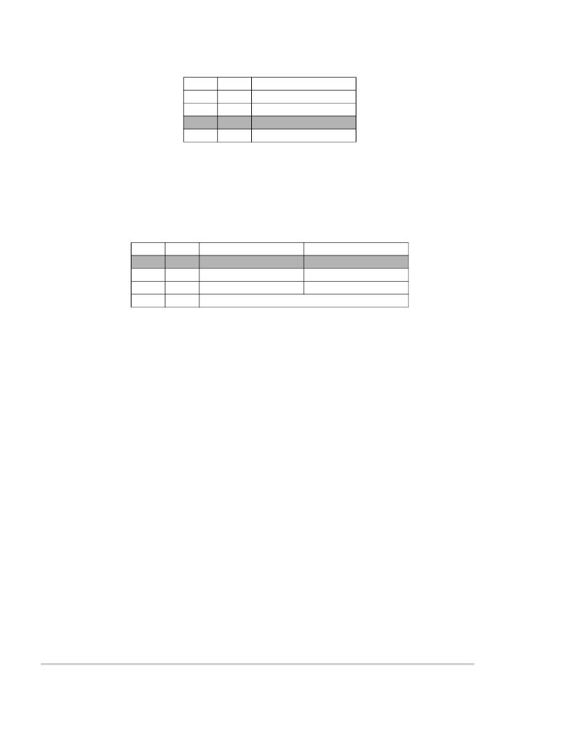
Table 9: Data Rate selection
DR1 DR0 Selected Ratio
0 0 1.0 - 1.4 kBd
0 1 2 - 2.7 kBd
1
0
4 - 5.3 kBd
1 1 8.6 - 10.6 kBd
- MG sets the mixer gain:
0 = Normal,
1 = -17dB (typical).
- MS switches the MIXOUT pin:
0 = To the mixer output,
1 = To the IF input.
Table 10: Mixer and MIXOUTconfiguration
MG
MS Mixer Gain MIXOUT
0
0
Normal
Mixer output
0
1
1
1 Normal IF input
0 Reduced Mixer output
1 Forbidden, mixer test mode only
The combination MG=1, MS=1 is forbidden in any application. It configures the receiver in a test mode where
the mixer runs at f VCO /4.
- PG sets the phase comparator gain (see “The local oscillator PLL” chapter, page 4):
0 = High gain mode,
1 = Low gain mode.
STATE MACHINES
AFTER POR RESET STATE MACHINE
There are 3 different modes for the receiver.
Sleep mode corresponds to the low power consumption mode:
- if SOE=0, the whole receiver is shutdown,
- if SOE=1, the strobe oscillator remains active.
Configuration mode is used for writing or reading the internal registers. In this mode, the SPI is slave and the
receiver is enabled. The crystal oscillator is running and generates the clock for the SPI. This implies that before
the circuit is in sleep mode, a delay corresponding to the crystal oscillator wake-up time must be inserted
between the falling edge on RESETB and the start of the transmission on the SPI lines. The local oscillator is
running as well. This means that demodulated data can be read on DMDAT but are not sent by the SPI.
In Run mode , the receiver is enabled (crystal and local oscillators are running). It is either waiting for an RF
telegram or receiving one.
Figure 14 details the state machine after Power On Reset (POR). The state machine is synchronized by a
sampling clock at 615kHz (sampling period Ts=1.6μs), derivated from the crystal oscillator. The transition time
between state 1 and states 2 or 6 is less than 3 ′ Ts.
12
MC33591 Technical Data
For More Information On This Product,
Go to: www.freescale.com
MOTOROLA
发布紧急采购,3分钟左右您将得到回复。
相关PDF资料
MC33593MOD868EV
BOARD EVAL MC33593 ROMEO2 RF
MC33690DWER2
IC STAND ALONE TAG READER 20SOIC
MC44CC375AVEFEVK
CCEVK NEJA EVAL KIT
MCH3374-TL-E
MOSFET P-CH 12V 3A MCPH3
MCH3375-TL-H
MOSFET P-CH 1.6A 30V MCPH3
MCH3377-TL-E
MOSFET P-CH 20V 3A MCPH3
MCH3377-TL-H
MOSFET P-CH 3A 20V MCPH3
MCH3382-TL-H
MOSFET P-CH 2A 12V MCPH3
相关代理商/技术参数
MC33591MOD434
功能描述:BOARD EVALUATION FOR MC33591 RX RoHS:否 类别:RF/IF 和 RFID >> 过时/停产零件编号 系列:- 标准包装:1 系列:- 类型:用于 200/300 系列的欧盟开发套件 适用于相关产品:Zensys RF 模块 所含物品:开发板,模块,编程器,软件,线缆,电源 其它名称:703-1019Q3225667
MC33591MOD434EV
功能描述:开发板和工具包 - 无线 MC33591 (ROMEO2) RF EVAL RoHS:否 制造商:Arduino 产品:Evaluation Boards 工具用于评估:AT32UC3L 核心:AVR32 频率: 接口类型:USB 工作电源电压:5 V
MC33592FTA
功能描述:IC RF RECEIVER 315,434MHZ 24LQFP RoHS:否 类别:RF/IF 和 RFID >> RF 接收器 系列:- 产品培训模块:Lead (SnPb) Finish for COTS 产品变化通告:Product Discontinuation 09/Jan/2012 标准包装:50 系列:* 频率:850MHz ~ 2.175GHz 灵敏度:- 数据传输率 - 最大:- 调制或协议:- 应用:* 电流 - 接收:* 数据接口:PCB,表面贴装 存储容量:- 天线连接器:PCB,表面贴装 特点:- 电源电压:4.75 V ~ 5.25 V 工作温度:0°C ~ 85°C 封装/外壳:40-WFQFN 裸露焊盘 供应商设备封装:40-TQFN-EP(6x6) 包装:托盘
MC33592FTAE
功能描述:射频接收器 UHF RECEIVER RoHS:否 制造商:Skyworks Solutions, Inc. 类型:GPS Receiver 封装 / 箱体:QFN-24 工作频率:4.092 MHz 工作电源电压:3.3 V 封装:Reel
MC33592FTAER2
功能描述:射频接收器 UHF RECEIVER RoHS:否 制造商:Skyworks Solutions, Inc. 类型:GPS Receiver 封装 / 箱体:QFN-24 工作频率:4.092 MHz 工作电源电压:3.3 V 封装:Reel
MC33592FTAR2
功能描述:IC RF RECEIVER 315,434MHZ 24LQFP RoHS:否 类别:RF/IF 和 RFID >> RF 接收器 系列:- 产品培训模块:Lead (SnPb) Finish for COTS 产品变化通告:Product Discontinuation 09/Jan/2012 标准包装:50 系列:* 频率:850MHz ~ 2.175GHz 灵敏度:- 数据传输率 - 最大:- 调制或协议:- 应用:* 电流 - 接收:* 数据接口:PCB,表面贴装 存储容量:- 天线连接器:PCB,表面贴装 特点:- 电源电压:4.75 V ~ 5.25 V 工作温度:0°C ~ 85°C 封装/外壳:40-WFQFN 裸露焊盘 供应商设备封装:40-TQFN-EP(6x6) 包装:托盘
MC33593FTAE
功能描述:射频接收器 UHF RECEIVER RoHS:否 制造商:Skyworks Solutions, Inc. 类型:GPS Receiver 封装 / 箱体:QFN-24 工作频率:4.092 MHz 工作电源电压:3.3 V 封装:Reel
MC33593FTAER2
功能描述:射频接收器 UHF RECEIVER RoHS:否 制造商:Skyworks Solutions, Inc. 类型:GPS Receiver 封装 / 箱体:QFN-24 工作频率:4.092 MHz 工作电源电压:3.3 V 封装:Reel
